CIRCUIT BREAKER TESTING TECHNOLOGY
Paul E. Schoen, President
P S Technology, Inc.
March 26, 1997
Portions of this article were originally published
by:
Lake Publishing Corporation
17730 West Peterson Road
P.O. Box 159
Libertyville, IL 60048-0159
It appeared in Electrical Manufacturing Magazine September
and November, 1989
This article will explore the technology of testing high current
circuit breakers. It will touch upon various aspects of circuit
protection, protective devices, and need for testing, but will
focus upon the practical aspects of generating and measuring the
high currents required in the testing of circuit breakers.
CIRCUIT PROTECTION
Circuit protection has been a factor in electrical systems since
the beginning of the Electrical Age, and has matured over the
years. Any system involving electricity has a source of power,
conductors, and a device which uses the power. If any element
fails, damage could occur, and protective devices may be used
to limit its extent.
Of primary consideration is the maximum available power. Batteries
and generators have maximum short circuit currents which are limited
by their voltage and internal impedance, and severe overheating,
mechanical stresses, and explosion may occur if excessive fault
currents flow for more than a brief time.
The conductors carrying power to its destination are rated for
a certain amount of continuous current, based on ambient temperature,
insulation material, and type of conductor. Excessive currents
cause a temperature rise over time that will eventually damage
the insulation or even cause the conductor to melt.
In a power distribution system, where several users of power are
connected to a main source, it is usually desirable that the failure
of one section of the network should not disturb the operation
of other sections. If protective devices are chosen properly,
or coordinated, this effect may be achieved.
PROTECTIVE DEVICES
A protective device monitors one or more factor affecting safe
operation of an electrical system, and produces an appropriate
response in case of a fault condition. The factors include current,
voltage, wattage, phase angle, frequency, temperature, and pressure.
The appropriate response may be a visual, audible, or electrical
signal, or a physical action which actually interrupts the current
or otherwise eliminates the fault condition. Additionally, this
response may be intentionally delayed by some period of time,
which is often inversely proportional to the magnitude of the
fault.
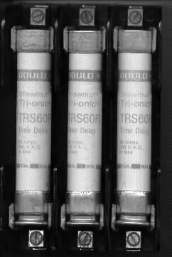
Fuses such as these provide inexpensive and reliable protection from catastrophic failures and extreme fault currents.
| The devices covered by this article will be limited to those that monitor the amplitude of a current, and react by interrupting that current when it exceeds a predetermined value. The time delay from sensing the overcurrent to the actual interruption is assumed to be determined by the amount of overcurrent as well as other factors, such as ambient temperature and recent history of overcurrents.
The simplest device is the fuse or fusible link. This is basically a conductor which is designed to melt in a specified period of time at a given current, thereby breaking the circuit. Fuses are inherently the most reliable and least expensive protective device, because of their simplicity and immunity to environmental contamination. Fuses, however, are inconvenient if the circuit is subject to frequent fault conditions, since they must be physically replaced after each operation. In order to provide greater convenience and versatility, circuit breakers were developed, which could be reset after being tripped by a fault condition, and could be used to disconnect the circuit manually.
|
| The simplest circuit breakers use the principle of electromagnetic trip with no intentional time delay. The current through a coil generates a magnetic field which exerts a force against a preset trip mechanism. When this force is large enough, the trip mechanism begins to operate, and after a period of time, determined by the amount of force, inertia, and other mechanical factors, the contacts open.
Since many electrical devices exhibit a considerable inrush current upon turn-on, or may produce temporary surges of current during normal operation, it is often necessary to provide a time delay. Circuit breakers that meet this requirement may use various combinations of heating coils and mechanical devices such as dashpots, or may employ electronic circuitry. The electronic type may have complex testing requirements, and will not be covered here.
| 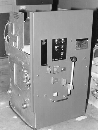
This is a typical large draw-out air circuit breaker, removed from its cubicle.
|
A special type of time-delay circuit breaker is the motor overload
relay. This type of device is used most often for the protection
of electrical motors driving compressors, where a temporary locked
rotor condition may occur. In this case, a thermal element trips
the contacts after a moderate period of overcurrent, waits for
a time, then resets itself, again applying power to the motor.
Sometimes there are other situations where fault conditions may
be temporary, as in the case of lightning strokes or tree branches
falling briefly across a power line. In such cases, the protective
device may be in a remote area, and it would be inconvenient to
require someone to reset it after such transient incidents. For
this reason, devices known as reclosers were developed. When a
fault occurs, the recloser trips, waits for a short period of
time, and then resets itself. If the fault remains, it will cycle
through a series of trips and recloses, during which the cause
of the fault may be removed, or it eventually locks in a tripped
condition. The testing of reclosers is similar to that for circuit
breakers, but will not be covered in this article.
The last type of protective device to be discussed is the protective
relay. This device consists of a circuit which monitors one or
more factors affecting the electrical system, such as current,
voltage, frequency, etc., and closes a circuit which trips one
or more remotely located trip devices. The testing of protective
relays has some commonality with circuit breaker testing, but
will not be covered here.
THE NEED FOR TESTING
| Almost all people have experienced the effects of protective devices operating properly. When an overload or a short circuit occurs in the home, the usual result is a blown fuse or a tripped circuit breaker. Fortunately, few have the misfortune to see the results of a defective device, which may include burned wiring, fires, explosions, and electrical shock.
It is often assumed that the fuses and circuit breakers in the home or industry are infallible, and will operate safely when called upon to do so ten, twenty, or more years after their installation. In the case of fuses, this may be a safe assumption, because a defective fuse usually blows too quickly, causing premature opening of the circuit, and forcing replacement of the faulty component. Circuit breakers, however, are mechanical devices, which are subject to deterioration due to wear, corrosion, and environmental contamination, any of which could cause the device to remain closed during a fault condition. At the very least, the specified time delay may have shifted so much that proper protection is no longer afforded to devices on the circuit, or improper coordination causes a main circuit breaker or fuse to open in an inconvenient location.
| 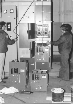
These technicians are removing some large air drawout circuit breakers from their cubicles for testing and servicing. Regular maintenance should be scheduled and electrical testing should be performed to ensure reliability of the electrical protection system.
|
TESTING METHODS
The manufacturers of circuit breakers must test their designs
under actual operating conditions, which requires the application
of fault currents at the rated voltage. Under such conditions,
a circuit breaker will be subject to extreme mechanical and electrical
stresses. At the maximum interrupting rating, it may actually
be damaged or destroyed, but if the fault current is safely interrupted,
the circuit breaker passes the test.
Naturally, it is impractical and unnecessary to test circuit breakers
at full power in the field. It is generally accepted practice
to apply fault currents to circuit breakers at low voltage, in
order to test their time delay and instantaneous operating characteristics.
AC or DC high voltage insulation tests, as well as visual inspection,
normally suffice to determine if the breaker will function safely
under actual fault conditions.
| Some very high current circuit breakers employ current transformers, sense circuitry, and a trip signal to a set of main contacts, to perform the current interruption function. Although testing could be performed using the primary injection method, it may be very difficult and impractical. Therefore, a method called secondary injection is used, in which a current representative of the output of the CT's is applied to the sense circuitry, and the trip signal is monitored.
Crude functional tests are sometimes used in the field, but are not recommended. Soldering guns, which produce one or two volts at up to 200 Amperes, are sometimes applied to small breakers to see if they trip. However, the current is extremely variable, and there is no way to check the time/current characteristic. Another method is the application of DC current from an automotive storage battery, but this can produce currents large enough to damage the breaker, and can be very dangerous; moreover, the results are inconclusive.
| 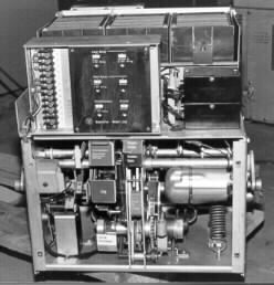
This view of a large draw-out air circuit breaker shows some of its complex electronic and mechanical components, all of which must work properly to provide reliable protection.
|
CURRENT GENERATION REQUIREMENTS
In order to understand the requirements for generating current
for the testing of circuit breakers, it is useful to examine the
actual operation of a breaker under low voltage test conditions.
When voltage is first applied to a device from a low impedance
source, such as the output of a transformer, current will begin
to flow according to the applied voltage and the overall impedance
of the breaker, its connections, and the internal impedance of
the test set. The current sensing apparatus will eventually operate
a trip mechanism, causing the main contacts of the circuit breaker
to open.
Some current will continue to flow as the contacts open, depending
on resistance, source impedance, applied voltage, stored inductive
energy, etc. For the purposes of low voltage testing, the duration
of such additional current flow is normally minimal, but in some
cases the change in impedance of the protective device may change
sufficiently during operation so as to affect the amount of current
flow, even to the point of inhibiting operation. This is not often
encountered in simpler devices such as circuit breakers, but is
very commonly seen in oil reclosers.
For the purposes of this discussion, the effects of using a low-voltage
source for testing will be explored. Most test gear uses an arrangement
of step-down transformers to generate a voltage which can be varied
to produce currents in the device under test ranging from well
under its nominal operating current to at least six times, and
up to twenty times, this value. At any given test current, the
combined impedance of the test set and the device under test interacts
with the selected output voltage to produce that current. If any
one of these factors vary, the test current will also vary.
The applied voltage may change due to variations in line voltage,
which may be caused by changes in load, fluctuations in generator
voltage, and heat generated variations in line resistance. Some
of these effects are very slow and minimal in overall effect,
while others may cause essentially instantaneous changes in voltage,
and the resultant current. Line voltage may also exhibit some
distortion (cyclic variations from true sinusoidal waveform),
which may cause related distortion in the output current.
The test set impedance will generally remain fairly constant for
a given setting of output voltage, but may vary considerably for
various combinations of input voltage, input taps, output taps,
and vernier settings. Heating effects often necessitate changes
in these settings, resulting in impedance changes. Other factors,
such as transformer design, wiring size, conductor routing, and
connector resistance, will also produce greatly varying test set
impedance for the same output current.
The impedance of the device itself will also affect overall current,
and has the greatest likelihood of causing large, measurable changes
in current during its operation. The operating coil of an interrupting
device is largely inductive, and its impedance is directly related
to its magnetic field. This field will change when any movement
occurs in nearby ferrous objects, particularly its operating mechanism.
Depending on its construction, this will cause various amounts
of inductance change, which will have some effect on the test
current. If this effect is great enough, and device is not fully
committed to trip at this point, operation could actually be inhibited.
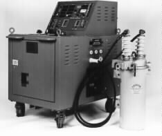
This is an EIL ORT-560 Recloser Test Set, with a typical recloser. The test set uses resistors to regulate the output current.
| Some improvement may be made by increasing the impedance of the test current source enough to swamp out the effects of impedance change in the device under test. This is already being done in the some recloser test sets, because of the very large impedance changes of oil reclosers, which can be as great as 5 to 1. However, without an active source which electronically regulates the current, practical limitations dictate that some variation in test current must be tolerated. This fact indicates that the measurement technology must somehow compensate for unavoidable distortion, and still produce meaningful test results that correspond to the manufacturer's published time/current curves.
|
PRACTICAL CURRENT GENERATION
The generation of high currents for practical testing of circuit
breakers is basically fairly simple. First, it is necessary to
know the impedance of the circuit breakers to be tested, as well
as the impedance of all connecting cables and buswork, to determine
the voltage required to produce the test currents. Typically,
this is in the order of one to 24 volts.
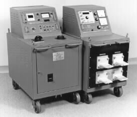
The 50,000 amp EIL BTS-500S was the top of the line for many years. It used a single E-I output transformer and tapped input autotransformer. Many are still in use today.
| In order to minimize the power requirements, it is best to have a range of output taps on a transformer, to match the circuit breaker impedance as closely as possible. The power rating of the transformer should be chosen to provide just enough power for the expected range of circuit breakers to be tested, at a duty cycle representative of actual test requirements. It should be noted that a typical transformer capable of 1000 amperes continuous can produce 2000 amperes for ten minutes in a half-hour interval (33% duty cycle), and can produce a maximum of 10,000 to 20,000 amperes peak current into a short circuit, for several tenths of a second, enough to trip a circuit breaker instantaneously. Once a suitable output transformer rating is determined, the actual design of the transformer must be addressed.
|
The simplest design, used in many older test sets, uses a single
E-I core, with a primary winding of 240 or 480 VAC. The secondary
consists of heavy copper wire or buswork, with one common connection,
and two or three taps for several ranges of output current and
voltage. The disadvantages of this design are (1) the necessity
of providing a continuously variable source from zero to maximum
voltage at full current capacity, and (2) the inefficiency of
having unused windings when operating at the highest current,
lowest voltage tap. The driving source for the transformer is
either a large, multi-deck variable autotransformer, or a multi-tap
autotransformer with a boost transformer and vernier. The advantage
of the multi-tap autotransformer is the capability of choosing
among a range of input voltages.
| Later designs, for larger test sets, employ an array of several E-I cores, with two identical series output windings, which could be connected in series or parallel for more efficient selection of output voltage/current rating. In some designs, one of the cores is made about half the size of the others, so that a buck/boost configuration with a smaller vernier can be used. Overall weight and size can be reduced substantially, since the primaries of the main elements are either shorted or connected directly to the input supply voltage. A disadvantage of this design is that only one input voltage may be used. Multi-tapped primaries and series/parallel connection of the vernier autotransformer could allow other voltages, but would be cumbersome to change in the field.
| 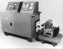
The EIL BTS-1000 used a multi-stage output transformer with series/parallel connections. It could produce over 100,000 amperes into a short circuit, and was capable of testing the largest circuit breakers in general use.
|
A new variation on this design is now being developed, using an
arrangement of toroidal transformer cores and buswork. The well-known
advantages of toroids include greater efficiency, smaller size,
lighter weight, and less acoustic and electrical noise. The configuration
under development also allows selection of three output arrangements,
for better matching of impedance to the device under test. A further
advantage is modular construction, which permits flexible design
and lower cost.
Another factor involved in generating test currents is distortion
of the current waveform. Since circuit breakers are largely inductive,
an applied voltage starting at a zero crossing will generate a
high current transient, known as DC offset. This cannot be controlled
with contactors, but newer test set designs use SCRs, which can
be gated to turn on at or near the voltage peak, resulting in
less DC offset and more repeatable readings.
CURRENT SENSING TECHNOLOGY
Circuit breaker testing requires the measurement of currents from
less than one ampere to about 100,000 amperes. There are very
few devices which can measure such a wide range of current to
the required accuracy, which is in the order of 1%.
The most accurate current measurement device is probably the shunt,
which is a precision resistor calibrated using DC, to accuracies
of 0.1% or better. AC accuracy at line frequencies is likely to
be nearly as good, but inductance may cause inaccuracies at higher
frequencies. Shunts are readily available up to 10,000 amperes,
and may be overloaded to ten or more times their rating for short
periods of time as applicable to breaker testing. One limitation
of the shunt is its low output voltage. A 10,000 ampere shunt
will produce 100 millivolts at its rated current, but only one
millivolt at 100 amperes. This means that a 1% error at 100 amperes
represents only 10 microvolts, which may be very small in proportion
to the several volts of common mode voltage, and hundreds of volts
and thousands of amperes that are generated in the near vicinity
of the measurement equipment. Another drawback to the shunt is
its large power requirement, or burden. The 10,000 ampere shunt
requires 1000 watts at its rated current, which is tolerable,
but at 20,000 amperes this grows to 4000 watts, and at 100,000
amperes, 100,000 watts is consumed. Shunts are very useful for
calibration purposes, but have limited use in practical AC high
current test sets.
The traditional way to measure AC current at line frequencies
is the iron core toroidal current transformer, or donut CT. This
device has isolation, low burden, low cost, high output, and good
accuracy. Its limitations are its limited useful range, and inability
to measure DC components of the current waveform. Also, it is
subject to saturation at high currents, with resultant waveform
distortion, and non-linearity at lower currents due to required
magnetization currents. A multi-tapped primary could be used for
various current ranges, but this is unwieldy for a practical high
current test set.
A popular alternative to iron-core CT's is the air-core CT, which
may be configured as a toroid, a two-pronged fork, or other arrangement.
A very simple CT of this type is an air-core inductor placed on
or near the conductor of the current to be measured. The output
of an air-core CT is a voltage, which is proportional to the differential
(rate of change) of the current. This is relatively easily converted
to read the actual current by performing an integration, which
may be done with a resistor and a capacitor. A great advantage
to the air-core CT is its wide operating range, demonstrated to
be at least 1000 to 1, combined with its other qualities of low
cost, low burden, wide frequency response, high isolation, and
high output. Its chief limitation is its sensitivity to stray
magnetic fields, making its placement around the conductor and
within the test set critical.
CURRENT AND TIME MEASUREMENT REQUIREMENTS
Most overcurrent protective devices operate on the true-RMS value
of the applied current. Electromagnetic breakers operate on the
strength of a magnetic field, and are generally rated to work
on DC as well as AC. Highfrequency components are integrated out
due to inductance and physical mass of the operating mechanism.
Time-delay devices usually use heaters or mechanical dashpots,
which operate on the force-generating or heating effect of the
current, which is the definition of true-RMS. Thus, if the measuring
circuitry can read the true-RMS value of the applied current waveform,
inaccuracies caused by distortion would be minimized.
Circuit breakers are designed to conform to published time-current
curves to an accuracy of about +/- 20%, which may apply to either
current or time. In general, a circuit breaker is specified not
to trip at its rated current value, and must trip at a current
of perhaps 150% of its rating. This means that a 20 Ampere breaker
may carry up to 29 Amperes forever, but must trip within several
minutes at 30 Amperes. Time delay variations of 20% or more are
usually reasonable, and are generally specified from about 200%
to as much as 1200% of rating. At higher currents, breakers are
expected to trip instantaneously, or with no intentional delay,
which is typically no greater than 0.02 seconds, or about one
cycle.
CURRENT MEASUREMENT TECHNOLOGY
The earliest high current measuring systems used iron vane analog
meters in conjunction with iron core CT's. Pulse current of short
duration was measured by using a pointer preset mechanism, which
held the needle to the expected current. When the current pulse
occurred, if the needle jumped, the preset amount of current was
assumed to have been reached. Current measurement was very approximate,
and timing was performed using electromechanical clocks, started
at the time of initiation of output, and stopped when the breaker
opened.
For reasons stated above, air-core CT's soon replaced the iron
core transformers. The output of the CT first goes through a voltage
divider, which selects an appropriate range. An integrator derives
the true current signal, which is passed to a precision rectifier
circuit. Its output is the absolute value of the input, and the
RMS value is not changed. The average of this signal is then obtained
by another integrator. Assuming a sinusoidal waveform, the RMS
value may be calibrated as 1.1 times the average, but moderate
distortion may cause errors of up to 10%.
This type of measurement is generally adequate for moderately
distorted waveforms of sufficient duration to read a value visually,
typically 1 second or longer. However, shorter duration pulses,
even one cycle (0.0167 sec) or somewhat less, are encountered
with some regularity in breaker testing.

The "Duffers" Memory Ammeter, used in many EIL circuit breaker test sets, incorporated peak reading circuitry, and used blanking to reduce error from DC offset. It was soon replaced by the Accu-Amp, which used a true-RMS converter IC in conjunction with a fast-attack, slow decay circuit.
|
One method of pulse measurement is a peak reading meter, which
reads the peak absolute value of the waveform. For pure sine waves,
this is accurate, since the RMS value is simply 0.707 of the peak
value. However, distortion can produce errors of up to 30%. Another
problem is that, depending on the phase angle of the initial portion
of the waveform, a "DC offset" is produced, due to circuit
inductance, and could have a peak value as much as twice normal.
It is possible to "blank out" a number of measurement
cycles, but this is impractical for very short pulses approaching
one cycle.
An improved approach is a track-and-hold circuit, which may be
adapted to the more accurate average-responding circuit. In this
case, the integrated output of a precision rectifier is gated
to a storage element, typically a capacitor, while the amplitude
is above a preset value. A comparator is used to drive the gate
while the actual signal remains above threshold. The problem here
is that an integrator with a ripple (or error) of less than 1%
also has a rise time much greater than one cycle, so either quick
pulses are read as low, or random errors of greater than 1% are
experienced.
One solution which has worked to some degree of success is a "fast
attack, slow-decay filter", which is a modified peak-hold
circuit with an intentional rate of decay. This eliminates some
of the effects of DC offset at the beginning of a long pulse,
but there are still necessary trade-offs in response time and
accuracy, even for sine wave signals. Practical accuracies of
5% or somewhat better are obtainable for roughly sinusoidal signals
of at least two or three cycles duration and minimal DC offset.
An improvement in true-RMS measurement technology has been made
with the introduction of true-RMS to DC converter IC's, which
perform a true-RMS conversion function using log and anti-log
amplifiers, with an intermediate averaging function using a capacitor.
With the proper components, a settling time of about 20 mSec with
1% accuracy is possible, but this is still insufficient for sub-cycle
pulses. Combined with a fast-attack/slow-decay filter, accuracies
approaching 2% on reasonably clean pulses of 2 cycles or more
can be obtained.
TIMING MEASUREMENT TECHNOLOGY
The measurement of delay trip times of several seconds on three-phase
breakers is no problem. Early technology employed electromechanical
clocks, which started when the test current was applied to the
breaker, and stopped when it tripped, as sensed by an auxiliary
connection to an unused contact. The typical error of about a
tenth of a second is acceptable for trip times of several seconds.
This method cannot be used, however, for single pole breakers
without unused or auxiliary contacts.
Such breakers required the use of a "current latch"
circuit, which served the dual purpose of providing a signal which
could maintain the test current through the breaker until it tripped,
and operate the timer. A relatively simple circuit, consisting
of a rectifier, filter, and threshold detector, can be used for
the latch requirement.
Instantaneous trip time measurements, in the order of several
cycles, present another challenge. Because of the turn-on delay
of a contactor or SCR, and operating times of electromechanical
relays, it is necessary to use current measurement techniques
for such fast timing measurements. If the current waveform is
observed on an oscilloscope, it is usually fairly easy to determine
the start and stop points, even when there are discontinuities
and other noise in the waveform. However, designing a circuit
to do this is more difficult. If a simple comparator, set at 5%
of maximum value, is used on the rectified waveform, a series
of pulses of varying duty cycle is formed. This signal can be
filtered and sampled by a second comparator, which should produce
a step function which represents the time of the pulse. Using
such circuitry produces accuracies of 5 to 10 milliseconds on
most pulses.
DIGITAL ELECTRONICS AND MICROPROCESSORS
| With analog-to-digital conversion and microprocessor-based signal analysis, greater accuracy has been made possible. Essentially, the signal is sampled by an A/D converter at several times the fundamental frequency, and the values stored in memory. Various algorithms, implemented in software, read the current, and determine starting and stopping points. A true-RMS calculation is performed on a selected part of the waveform, and the accuracy increases with the number of samples. Post-processing can also be used to adjust for amplitude effects, and the actual waveform may be saved to a disk, viewed on a screen, or plotted. The accuracy obtainable by using such methods should be in the order of 1% for amplitude, and 0.005 seconds for time.
| 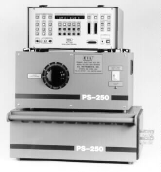
The EIL PS-250 was one of the first breaker test sets to use a microprocessor, but it retained some of the original analog signal preprocessing. Its major advantages were programmable auto-jog and current hold, and data storage, retrieval, and report printing.
|
Several new systems were developed in the late 80s and early 90s.
The ubiquitous and ever more economical IBM PC was used in several
designs. A recloser test system was developed using a proprietary
plug-in board for data acquisition and control. It was incorporated
in a rack-mounted computer that was an integral part of the test
set. The problem of determining the true-RMS value of the severely
distorted waveforms was solved by performing a mathematical analysis
of the stored A/D samples. The software also interfaced to a database
program for data storage, test result verification, and report
generation.
An early attempt to use the PC for circuit breaker testing used
a passive backplane system with an off-the-shelf data processing
board in conjunction with a proprietary interface to a keyboard
and LCD display. This eliminated the awkward CRT display and standard
PC keyboard, but added considerable cost, and eliminated certain
useful functions, such as waveform display and custom reports.
As the cost of portable PCs dropped, it soon became much more
cost-efficient to use that platform, and the proprietary interface
was never put into production.
One of the first practical systems using a laptop computer was
developed in the early 90s, and was used in some new circuit breaker
test sets as well as a retrofit system for older units. A database
program was also developed for this design. However, it was difficult
to install the A/D board and proprietary interface in the portable
computer, and the interface was delicate and susceptible to electrical
noise and mechanical damage. Nevertheless, it is still in use
in some breaker test sets currently in production.
As the convenience and versatility of notebook style PCs became
increasingly attractive and inexpensive, P S Technology pioneered
the design of a parallel port interface that could be used for
data acquisition and control. Its first application was for recloser
testing, in the form of the ORTMASTER accessory, which was designed
as a retrofit for existing test sets. It used an MSDOS program
to display currents and trip times, and interfaced to a database
program for immediate verification of results to manufacturer's
curves.
The same basic hardware, with some modification and a different
software program, was incorporated in a retrofit system for circuit
breaker testing. It is marketed by P S Technology as the STABMASTER.
Although the PC-based system has many advantages, it was found
to be too complex and fragile for many circuit breaker testing
applications. In response to these concerns, P S Technology developed
the BTSMASTER, which is a self-contained measurement and control
package. It uses a Z-180 based microprocessor core, and is housed
in a rugged rack-mountable enclosure that is mechanically and
electrically compatible with the EIL Accu-Amp. This feature makes
it ideal for retrofit applications. The pushbutton controls and
dual LED readouts are designed for simplicity of operation and
reliability, while the internal circuitry and firmware are optimized
for accuracy.
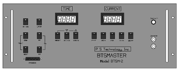
The BTSMASTER, P S Technology's latest breaker testing instrument, incorporates an A/D converter and microprocessor for true-RMS reading of current, accurate reading of trip times, and a convenient programmable on time feature for auto-jog operation.
|
Future developments in circuit breaker testing will probably focus
on simplicity, reliability, accuracy, and affordability. This
will most likely be accomplished by a modular approach, with a
simple, rugged main output unit, integral initiation and adjustment
controls, a self-contained monitor and control unit, and interface
capability to separate computer systems for enhanced operation.
PRACTICAL TEST SYSTEMS
Circuit breaker test sets should be designed according to requirements.
For most purposes, it is sufficient to test circuit breakers at
one or two representative points on the time-current delay curve,
to a timing accuracy of +/- 0.1 seconds, and determine instantaneous
trip current within about 5%. Very simple and inexpensive test
sets may be built with these specifications.
With microprocessor technology being inexpensive and versatile,
it is now possible to provide increased accuracy of testing, while
also adding certain features to save time and reduce error. Test
set automation may include an auto-jog feature to determine instantaneous
trip current, as well as automatic adjustment of output current
to a preset value for long-time testing. The addition of a computer
can add additional benefits of automatic set-up of the test set
for various tests on standard breaker types, and interface to
a database of test results for subsequent analysis.
CONCLUSIONS
The most important idea that should be derived from this article
is the need to perform regular testing on circuit breakers. We
rely on their correct operation for protection from the extreme
hazards that can be produced by electricity, but only with proper
testing can we have true confidence.
If it is agreed that regular testing is necessary, it should also
be apparent that reasonable accuracy must be guaranteed. This
should be relatively easy to accomplish by means of proper design
and construction of specialized test equipment. Older test sets
should be carefully tested for accuracy and reliability, and if
found to be deficient, they should be replaced or retrofitted
with more modern measurement and control systems.
Finally, it is important to analyze the overall picture, on the
basis of cost. If circuit breakers are tested regularly, the safety
of the installation should be better, possibly resulting in lower
insurance rates. If circuit breakers can be tested more quickly
with a new, computer-based test system, less time spent in testing
will result in monetary savings. Most important, if a comprehensive
test program results in the saving of even one life, any effort
or expenditure must be considered worthwhile.